A Brochure issued with the Compliments of the West Fife Area, Scottish Division of the National Coal Board on the occasion of the visit of The Mining Institute of Scotland to Bowhill Colliery on 12th September, 1953, forms part of Kenny Scott's collection of mining memorabilia. The contents of that Brochure detailing the Reconstruction Scheme for the Colliery have been reproduced for your interest.
BOWHILL COLLIERY
RECONSTRUCTION SCHEME
WEST FIFE AREA SCOTTISH DIVISION
NATIONAL COAL BOARD
FOREWORD
On behalf of the National Coal Board, it gives me great pleasure to welcome the members of the Mining Institute of Scotland to see part of the reorganisation scheme in operation at Bowhill Colliery. The scheme is briefly explained in this brochure.
One unusual feature for Scotland is the operation of the Balance Rope Clutch Drum Haulage, which hauls the 2½ ton mine cars a distance of 1,200 yards up a gradient of 1 in 4. The arrangements in the pit bottoms and on the surface are a big step forward in the right direction and have resulted in a considerable saving of labour.
The planning and completion of this project reflects great credit on all concerned and I would like to pay a special tribute to the Planning Department, the Electrical and Mechanical Engineers, and the Managerial Staff at the Colliery for the way in which this work has been carried through.
When the New Sinking is completed, and the new Coal Preparation Plant installed, Bowhill Colliery should make a substantial contribution to the increased output which is so necessary for the Scottish Division.
GEORGE MULLIN,
Area General Manager,
WEST FIFE AREA.
 |
GENERAL DESCRIPTION
Bowhill Colliery, comprising No. 1 Shaft sunk to the Five Foot seam at 218 fms. and No. 2 Shaft sunk to the Lochgelly Splint seam at 166 fms., is situated in Auchterderran Parish on the main public road between Lochgelly and Kirkcaldy.
Prior to the reconstruction scheme the pithead arrangements consisted of the usual gravity, elevating creeper and tub circulating system between the shafts and the tipplers. Coal, +3" size, is prepared on the five screening and picking table units and coal, -3" size, is cleaned in two 60 ton per hour Baum washer units. The steam for the two winding engines is supplied from three 40,000 lb./hour water tube boilers which also supply the colliery generating plant, viz.: one 3,000 kW mixed pressure turbo-alternator and one 3,000 kW high pressure alternator.
The underground workings have been laid out on the orthodox longwall advancing system with coal cutters, face, gate and trunk conveyors to the loading points from which the coal was transported in 12 cwt. steel tubs by endless rope haulages to the pit bottom.
After careful examination of the main underground avenues, the extent of the workings, and the reserves then available to be worked, it was apparent that a more modern system of transport was essential to give improved results. In 1945 a scheme was prepared to completely reorganise the underground transport system by the introduction of 2½ ton mine cars, locomotive haulage, large balanced rope haulage to deal with the dip coal, and to introduce mechanical handling of cars wherever possible. The surface arrangements were also to be reconstructed to handle mine cars. This scheme also envisaged a total output of 1,800 tons saleable coal daily from both pits.
The reconstruction work in each pit was planned to be completed in definite stages. This involved the extension of the Five Foot dooks in No. 1 pit to the 360 fms. horizon and the development of the seams by cross-cut mine; the special development of the Smithy Seam by a rise mine from No. 2 pit bottom; the installation of a belt conveyor system with the loading point in the pit bottom; the provision of face room in No. 2 pit so that the colliery output would be maintained while No. 1 pit was temporarily shut down to enable the following reconstruction work to proceed. The installation of the balance rope haulage, car handling equipment in the pit bottom, and track laying for mine cars; the installation of car and coal handling arrangements on the surface during the same period; the restarting of No. 1 pit with mine car transport system; the reconstruction of No. 2 pit involving the installation of car handling equipment in the pit bottom and the completion of the surface arrangements.
The original scheme has been amended in keeping with present-day knowledge in mine car handling, but its main principles, as laid down in 1945, have been followed.
The reconstruction programme outlined above has almost been completed and mine cars are now in operation on the surface and throughout No. 1 and 2 pits.
No. 1 pit closed down in July, 1952, for the purpose of changing over from tubs to mine cars and restarted in mid-January, 1953. The change over to mine cars took place at No. 2 pit during the two weeks summer holiday period in July, 1953, without interruption of output.
 |
No. 1 Pit Bottom
The outstanding features comprise:
The spacious well-lit pit bottom designed to deal with the ultimate output of 900 tons saleable coal daily from the Five Foot dook and 218 fms. level avenues; the car handling equipment in the pit bottom; the arrangements for dealing with cars from the Five Foot dook avenue, including the 3-rail track system on the dook; the back shunt roadway into the pit bottom; and the 400 H.P. balance rope clutch drum haulage.
Load cars are received into the pit bottom from the 400 H.P. dook haulage in sets of 6 and when uncoupled gravitate forward to a creeper which elevates and discharges each car on to a transporter carriage. This carriage spots the car at the cage position where pneumatic decking rams are used. The onsetter controls and initiates all the car handling equipment in the pit bottom from a cabin on the empty car transporter carriage which is operated by electric/hydraulic power.
The off-coming empty cars are transported to the empty track and gravitate forward to the coupling position in the siding.
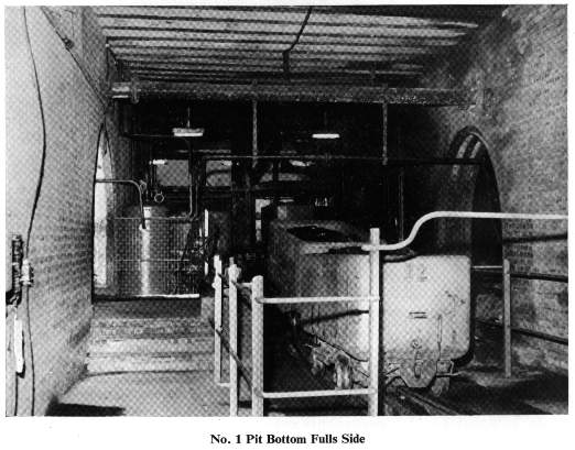
The creeper, load transporter carriage and decking rams are pneumatically operated and fully automatic. Interlocks are provided to prove the various stages in the sequence of operation.
This pit bottom layout is shown on plan No. 1 and the Five Foot dook track layout is shown on Appendix No. 1.
At present the output of 650 tons daily is got from the 360 fm. level where coal from the Diamond and Lochgelly seams is belt conveyed to the respective loading points, each controlled by one man, and serviced by 5 ton battery locomotive to the foot of the Five Foot dook. This locomotive will be replaced by an 8-ton battery locomotive whenever it is delivered.
No. 2 Pit Bottom
The reconstruction of No. 2 pit has now been sufficiently completed to allow mine cars to be introduced. The present saleable output of 1,000 tons daily is produced on a double shift from the Smithy and Lochgelly Seams and the coal is belt conveyed from the respective districts to the two loading points situated on the pit bottom level within 200 yards from the shaft. Each loading point is controlled by one man. A temporary direct haulage is used to service the inbye loading point but in the permanent arrangement a locomotive will be used.
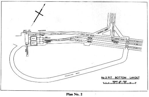
The car handling arrangement at the shaft bottom consists of an elevating creeper which discharges the individual load car on to a transporter carriage. This carriage transports the load car to the cage position where the decking is completed by pneumatic rams. The off-coming empty cars, which are transported by a pneumatically operated transporter carriage to the empty car track alongside the shaft, gravitate forward to a position suitable for being coupled by the onsetter. A small pneumatic ram is used to push the empty cars forward in the siding.
All the car handling equipment in the pit bottom is under the control of the onsetter who initiates the sequence of operations. The elevating creeper, load transporter carriage and decking rams are pneumatically operated and fully automatic. The empty car transporter carriage is also automatic in operation. Adequate provision is made by suitable interlocks to prove all stages in the sequence of operations.
The final arrangement of No. 2 pit bottom layout is illustrated on Plan No. 2.
 |
Surface
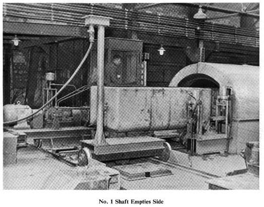
On the surface the method of handling mine cars is similar at Nos. 1 and 2 shafts and consists of the transporter carriage system whereby, by means of carriages on each side of the shafts the full and empty cars are transported to and from the tipplers. Pneumatic rams are used for decking the cars into the cages and tipplers.
Each banksman controls the carriages and rams from his cabin in the empty car carriage which also contains the hydraulic drive unit. The empty and load carriages move in unison, the drive being transmitted to the load carriage by means of Reynolds chain and sprocket wheels keyed to the common steel shafts.
Adequate provision is made by suitable interlocks at the cages to prove that the cages, carriages and air lock doors are in the correct position before the decking rams can be operated. Similar provision is made at the tipplers.
The coal from each tippler is discharged to an apron feeder, thence to the belt conveyor system by which the coal is conveyed to the screening plant. The system consists of two primary belt conveyors (one to serve each tippler and apron feeder) and three secondary belt conveyors placed at right angles.
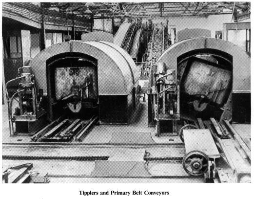 |
Two qualities of coal, and stone from mine drivages are wound from the shafts. Two of the secondary belt conveyors deal with one quality each while the third conveys the stone direct to the dirt hopper. Thruster operated ploughs on the primary belt conveyors divert the coal according to quality on to the proper secondary conveyor which delivers on to shuttle conveyor and thence into large hoppers from which the coal is fed to the screening plant. Suitable provision is made to deal with a third quality of coal if necessary, by using the third (stone) secondary conveyor.
 |
Quality selection is made by the respective banksman by selection switches placed at each tippler. The ploughs are automatically controlled through time relay mechanism The belt conveyor system is sequence controlled.
The general layout of the coal and car handling arrangements is shown on Plan No. 3.
 |
Personnel
On a single shift the pit bottom and Five Foot dook head transport personnel in No. 1 pit has been reduced from 12 to 3 and in No. 2 pit the pit bottom and haulage personnel has been reduced from 17 to 7. On the surface the personnel dealing with output to the screening plant, including the banksmen has been reduced on a single shift from 17 to 5.
The disposition of the manpower is illustrated on Appendix No. 2.
No. 3 Shaft Project
A previous brochure issued on the occasion of the official inauguration of the sinking describes the scheme as then envisaged.
Several changes have since been made in the method of car handling at banking level. Independent decking will be practised with a gravity, back-shunt, car circulating system as shown on Plan No. 6. Parallel head sheaves will be introduced in place of the tandem type previously proposed.
 |
TECHNICAL DATA
SURFACE
Air Seal Doors, No. 1 Pit . . Compressed air automatic doors, operated by cage.
Rams (Cages) . . . . .. Stroke 16'-0". Dia. 67/8". 85 lbs. per sq. in. c/a.
Rams (Tipplers) . . . . Stroke 14'-0". Dia. 67/8". 85 lbs. per sq. in. c/a.
Full Transporter .. .. Length 7'-8". Width 6'-0". Gauge 5'-5½ ". Wheel Base 6'-10".
Empty Transporter .. Length 10'-0". Width 9'-0". Gauge 5'-5½ ". Wheel Base 7'-6". Manual control. 10 H.P. motor. No. 3 V.S.G. gearbox.
Tippler . . . . . . Length 10'-4½". OJD Ring 7'-6". 5 H.P. motor. c/a automatic control.
Apron Feeder .. Length 28'-6" crs. Width 3'-7". I5 H.P. motor. 46.3 feet per min. Chain drive.
Primary Conveyors . . Length 105' crs. Width 42". 35 H.P. motor. 185 ft. per min.
Secondary Conveyors -- Length 76' crs. and 54' crs. Width 48". 20 H.P. motor. 290 feet per min.
Redd Conveyor . . . . Length 169 ft. crs. Width 48". 50 H.P. motor. 300 feet per min.
Shuttle Conveyor .. .. Length 21'-6" crs. and 31' crs. Width 60". 5 H.P. motor. 260 feet per min.
Ploughs . . . . . . Steel plate; electrically thruster controlled.
Surge Hoppers .. 14 ton capacity, hydraulic doors.
Compressors . . . . 50B Ingersoll Rand, fitted with aftercooler, filters and drainers.
Cars .. .. .. .. 106 cu. ft. 2½ tons capacity. Tare 27 cwts. Body length 9'-0". Width 3'-9 ". Depth 3'-1¾ ". Wheel Base 4'-0". Overall length 9'-9". Overall height 4'-6". Allen couplings.
UNDERGROUND
Shafts .. .. .. No. 1 Depth 218 fms. Rectangular 27'-4" x 11'. No. 2 Depth 166 fms. Rectangular 18' x 11'.
Cages .. .. .. Single deck with 1 car. Length 9'-10". Width 6'-10". Height 7'-3½ ". Weight 4 tons 4 cwts.
Cage Gates .. .. 8'-8" x 4'-2" Tubular frame-mesh covered. c/a automatically operated.
Empty Transporter .. Fabricated frame. Length 12'-6". Width 9'. Fitted with tilting platform. Manually controlled. 7½ H.P. motor. No. 3 V.S.G. gear.
Full Transporter . . . . Fabricated frame. Length 10'- 11½". Width 6'. Accommodates 2 cars side by side. Automatically controlled by c/a ram 4'-1½" stroke.
Bumper Stop .. .. Spring loaded recoil buffer type.
Decking Rams .. .. 16'-0" stroke. 67/8" dia. c/a 85 lbs. per sq. in.
Feeding Creeper .. .. Length 32'-2" crs. Chain speed 20' per min. 7½ H.P. motor. Epicyclic gear drive.
Compressor .. .. lngersoll Rand, 50B - 2 stage air-cooled, fitted with filters and drainers.
Balanced Rope Haulage .. 400 H.P. motor 3000V. 422 r.p.m. Liquid controller, Drums 7'-6" dia. x 4' wide. Hydraulic tooth clutch. Hydraulic post brakes. Drum speed 43.4 r.p.m. Average rope speed 18.15 ft. per sec. 6 cars per set.
Time Cycle .. .. Winding time on dook 4 min. 55 secs. Back shunt winding and tail changing 1min. 50 secs. Complete cycle 6 min. 45 secs.
Haulage Rope .. .. .. Preformed galvanised flattened strand. 6 strands, 9 over plaited core. Langs lay. 41/8" circ. 115/16" dia. 68.25 tons B.S.
Haulage House .. Height 25'. Width 26'- 8". Length 51'. Brickwalls 3½ ' thick. Fabricated roof joists 30' x 12" x 8" at 2'-6" centres, fitted with 5 ton hand operated travelling crane.
Back Shunt to Pit Bottom .. Length 130 yards. Gradient High Track 1 in 5.3. Gradient Low Track 1 in 9.1.
Track switches operated by automatic hydraulic pistons controlled by clutch on haulage.
Five Foot Dook .. .. Length 1,210 yards. Average gradient 1 in 4. Supported by 12' x 8' circle arches. Straight girders at pass-bye. 3 rail track on dook.
Rail Tracks .. .. 50 lb./yd. rails in 30 ft. lengths. 3 ft. gauge. 2 gauge plates per 30 ft. of track. Sleepers 5' x 8" x 4" laid at 2'-6" centres. 15 ft. between rope rollers.
Rope Rollers .. .. Steel's Patent Ball Bearing 12" long x 8" dia. on dook. 36 - Special Ball Bearing 24" long x 10" dia. capable of carrying a load of 6,000 lbs.
 |
 |